Overview
ProjectionDesigner is a setup tool for distortion correction and edge blending in multiple projection theater environments with various types of screen shapes. With this tool you can setup virtual projectors and a virtual screen in 3d environment to simulate the projection. You should run this tool in the actual environment to confirm the result of the simulation in real-time. After the setup, this tool exports the setup result as a ‘Projection data set’ – Distortion map image, Blending map image and View matrix file. This data set is basic information for projection in your environment.
You can use a movie converter tool with this data set to split and distort movie files for each projector. If you can link GLRC(OpenGL rendering composite library) with your OpenGL application, the application will load this data set for distortion correction and edge blending in real-time. With a special OpenGL replacement driver GLWare, you can also make these corrections for many OpenGL based applications without their source code.
This projection data set is simple, universal and not depends on implementation of applications. So you can make OpenGL or DirectX based 3d application, converter tools and etc based on this data set. From content creator’s point of view, you can expect that each theater has its own projection data set made by its user or vendor. So you can focus your energy on creating immersive content itself, not depending on actual theater environments.
ProjectionDesigner is a primitive, manual based setup tool. Basically it has no auto calibration functions such as (patented) camera-projector feedback algorithm. It’s important that there is at least one way to make the projection data set for free. If you want more automated, easy way to achieve the result, you should look for other tools.
Main features
- Virtual screen and projectors simulation in real-time 3d environment.
- Server / client synchronization for multiple PC projection environments.
- Supports plane, box, dome and any polygon-based shape screen.
- Projector’s position, direction, field of view, aspect ratio lens shift is configurable.
- 2d-based direct distortion / blend map shape manipulation.
- Image overlaying on projection image for reference.
- Simple Wavefront (.obj) format model importer for sample scene.
- Open format. Open source. Freely available!
Screenshots


Author
Toshiyuki Takahei (takahei<at>orihalcon.jp)
Platform
Windows 2000/XP
Licence
General Public Licence (GPL) / Commercial License (Dual License)
Download
Ver.1.0.0 Source and Windows binary
Ver.1.1.0 beta Source and Windows binary
Preparation
Hardware setup
When you setup the projection system with ProjectionDesigner, you should run it in actual projectors and PCs. In the following adjustment step, you’ll put virtual projectors and a screen strictly same as the actual ones, and project the simulated distortion images with the actual hardware to check the precise of result for more detail adjustment. For this reason, you need actual number of projectors to use, and one more screen to display the ProjectionDesigner user interface. You can use graphic cards with multiple display output, and networked PCs to prepare the enough number of displays.
ProjectionDesigner heavily uses OpenGL functions, especially off-screen rendering features such as a P-Buffer. You should use the latest graphic card and powerful PC you have. You should also install the latest graphic card driver.
To minimize the number of variable projector’s parameters, you should disable projector’s own distortion correction. You should also set the same parameters to zoom angle, lens shift, brightness and so on for all projectors you use.
Network setup
If you want to use ProjectionDesigner as server / client system over LAN environment, prepare your PC to be able to connect each other, and open a socket port (default port number is 55555) in firewall. I recommend to put ProjectionDesigner in a share folder where all PCs can access, and use the same program file. In this case, if you need many connections more than Window’s limitation (ex. 8 in WindowsXP), you should put the files in non-Windows based NAS.
Execute and Exit program
Boot as Standalone / Server
When you use ProjectionDesigner only in one PC, or use it on a server PC to do adjustment work, run projdesigner.exe program without arguments. If you want to specify a custom port number, use [-portno] option.
projdesigner.exe [-portno 12345]
Boot as Client
When you use ProjectionDesigner on a client PC which connected to projectors, run projdesigner.exe program with [-client] option. You should give a server address with [-address] option, and a custom port number with [-portno] option.
projdesigner.exe –client –address 192.168.0.10 [-portno 12345]
If the client program can not connect a server program, it tries to connect the server again and again. So you can boot a server after clients. But when you change number of clients or their host name, you should execute [File] > [Sync Clients] in menu for synchronization. It will be described in detail later.
Exit the program
You can quit standalone / server program by [File] > [Exit] in menu or click [X] button on the title bar. If your client program is displayed in full screen mode and menus are hidden, hit [Alt] + [Return] to cancel the full screen mode. You can also quit server and all client programs at once by [File] > [Exit All] in server’s menu. When you close the standalone / server program, all unsaved data will be discarded. Needless to say, save your data before exit the program!
Tutorial
In the following section describes each step of adjustment with ProjectionDesigner.
Execute programs
At first run projdesigner.exe on a server PC which has a screen to display the ProjectionDesigner’s adjustment user interface. Then run projdesigner.exe on client PCs with [-client] option and [-address] option with the server’s address as a client mode. If the clients successfully connect to the server, a message “Connected to server: server address” is displayed in their log area.
Setup screen shape
Click [Screen] tab in GUI panel, select a shape type in [Shape] group’s [Type] combo box. Set screen’s size depends on its shape type (unit is meter). In some screen shape, you can set wire frame resolution. If you can mark reference points on screen surface, or if your screen has some geometrical hint for reference, it’s highly useful for later adjustment to set the wire frame resolution to match the reference points. Set your screen’s position, rotation and scale in the [Screen] tab’s [Transform] group. Check [Wire frame] to display screen’s wire frame grid.
Add a Channel
Let’s add the first Channel. ‘Channel’ means a set which consists of one projector (‘Projector’) and rendering view (‘View’) for it. This first channel becomes the basis of the following other channel, so setup this channel accurately as much as you can.
Click [Channels] tab in GUI panel, click [Add] button to add a channel. In [Name] field you can set name of channel. Channel name must be unique among all channels.
Setup for projection
If you’re connecting the first channel’s projector to the server PC, click [Open Window…] button at the bottom of [Channels] tab. When a Projector Window appears, move it to the screen for projection, click somewhere in the window, then hit [Alt] + [Return] to toggle it to full screen mode.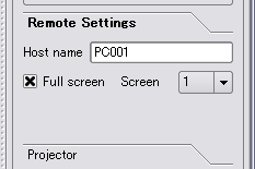
If you want to use a client PC for the first channel, click [Remote Settings] in [Channels] tab, and set client PC’s network host name in [Host name] field. Then click [Full screen] check box to full screen mode. After that, select [File] > [Sync Clients] in menu to synchronize between server and clients.
Now you have ProjectionDesigner’s main window and one other screen for projection of the first channel. In the following steps, you should adjust parameters by actually projecting the channel image on the screen.
Setup Projector's parameters
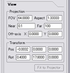
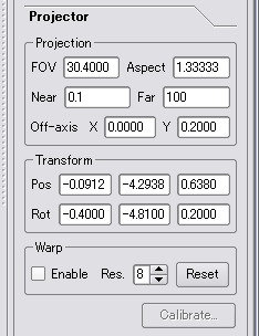 Click [Channels] tab in GUI panel, then click [Projector] to open a sub panel. In this panel, set [FOV] (projector’s vertical field of view in degree) and [Aspect] (projector’s aspect ratio, width/height. Ex. 1.33333 in XGA) values refer to its spec sheet. If your projector projects image to upper direction (most projectors do it), you should set [Off-axis X, Y] value (offset distance of image center at 1m from the projector’s center). Though these parameters are anytime adjustable in real-time, but I recommend to set precise values at first, and use the same value among all projectors.
Next, let's setup position and direction of the first channel’s Projector. In the 3D area there is a screen and projector’s projection area. Purpose of this step is to make the projector’s parameters to the actual one. But in most case it is difficult to measure the projector’s precise position and direction, you should use wire frame grid to match it to reference points or geometrical hints.
You can set parameter values in fields of [Projector] sub panel in [Channels] tab, or use the following keyboard shortcuts in 3D area. To use keyboard shortcuts, hit [Esc] key first to focus on 3D area.
I repeat that precise of first channel’s adjustment effects the following channels. Keep it in mind and setup precisely as much as you can.
Shortcut keys in 3D area
| Shortcut | Meanings |
|---|---|
| Mouse left drag | Rotation of 3D view. |
| Mouse right drag | Pan of 3D view. |
| Mouse wheel | Change distance of 3D view. |
| [Cursor key] | Change direction of Projector / View.* |
| [Home][End] | Change direction (roll) of Projector / View.* |
| [8][4][6][2] | Move Projector / View horizontally.* |
| [9][3] | Move Projector / View vertically.* |
| [+][-][*][/] | Change Projector / View ‘s lens shift value.* |
| [.][,] | Change Projector / View ‘s field of view.* |
| [F1]-[F5] | Change 3D view mode. |
| [Q] | Switch operation mode between Projector and View. |
| [T] | Switch move coordinate between Local and World. |
| [Space] | Change the current channel. |
| [A] | Show or hide coordinate axes. |
| [G] | Show or hide grid frame. |
| [I] | Show or hide information at upper left corner. |
| [Esc] | Focus on 3D area. |
* marked shortcut can adjust values in 1/10 accuracy with [Shift] key, in 1/100 accuracy with [Shift] + [Ctrl] keys.
Setup View parameters
 After the Projector setup, you need to setup View parameters. View means rendering area of the scene. In practice, you should adjust it as a view from the sweet spot (a point where you can see undistorted image in the theater), covering whole projector’s projected area on the screen surface. [Channels] tab in GUI panel has a channel list at the top of it. In this channel list, click [P](Projector) cell of the current channel twice to make it gray check, click [V](View) to make it gray check too. Now you can see blue Projector area and yellow View area on the screen surface. Let’s adjust the yellow area to cover whole blue area. Hit [Esc] key to focus on 3D area, [Q] key to switch View operation mode. Move the View to sweet spot where the best view position in the theater (ex. In dome screen, it should center of the dome – origin of the coordinate). Then change direction of the View by [Cursor key],[Home],[End] key, and change FOV by [.],[,] key to cover the whole blue area. More the View area becomes closer to Projector area, higher distortion rendering quality you’ll get.
Save your projection setup data
Now you finished the first channel setup. You should save the current setup data. Select [File] > [Save As] in menu to save the current data to xml file. Needless to say, you should save data frequently.
Setup other channels
For the next step, you should setup the next channel. In [Channels] tab in GUI panel, click [Add] button to add a new channel. Added new channel has the same parameter values as the first channel (last selected channel) as default. It’s useful when you setup left channel after right channel.
You can setup the new channel same as the first channel. When you adjust the Projector of the new channel, you’ll notify that when the two projector’s projection area are overlapped, edge of the projection area is visible in another projector’s projection image. It will be helpful hint for precise adjustment. With these hints you may be able to setup the following channels easier than the first one. But you should keep in mind that adjustment errors are accumulated in each channel. You still need to work precisely.
Test with a sample scene
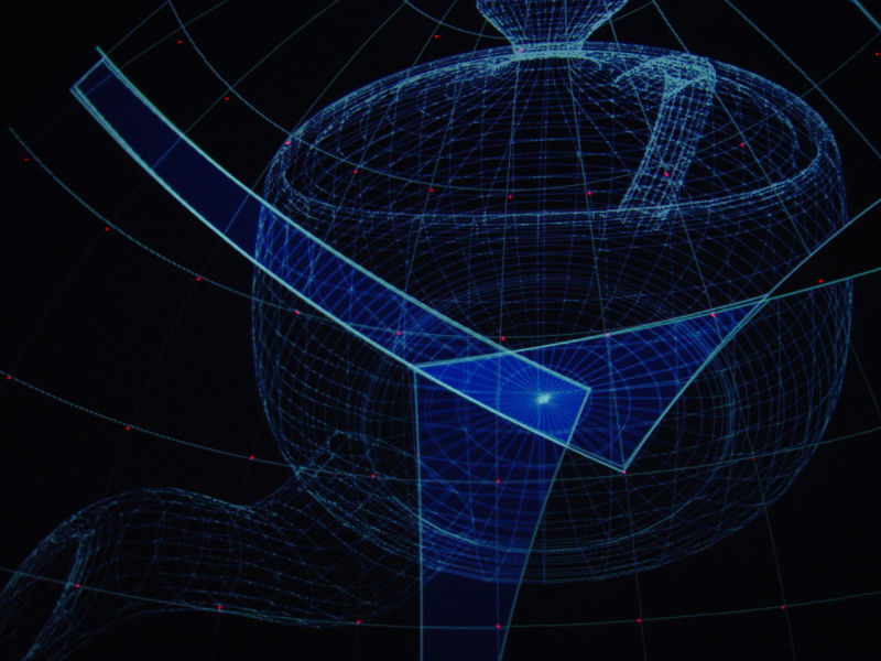
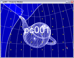
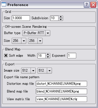
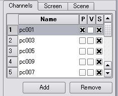 Now let’s see a sample scene with adjusted distortion correction. In channel list in [Channels] tab of GUI panel, make all [P](Projector) and [V](View) to be unchecked, and make all [S](Scene) to be checked by clicking header of the channel list. If you setup the projection correctly, you can see an undistorted teapot model from the sweet spot in your theater. If you need higher resolution for distortion correction, select [Edit] > [Preference…] in menu to open Preference Dialog, and then change [Size] value in [Off-screen Scene Rendering] group.
You can freely move the sample scene object. Select [Window] > [Scene Viewer…] in menu to open Scene Viewer Window. In this window, you can rotate the scene by mouse left drag, and change distance from the object by mouse wheel.
Warp distortion for detail adjustment
 In spite of the careful setup, accumulation of adjustment, screen shape and lens distortion error may cause small but unfixable projection error. For these cases, you can use direct image distortion to tweak the distortion correction. Keep in mind that this direct tweak does not reflect geometrical information. You must use it for tiny error only.
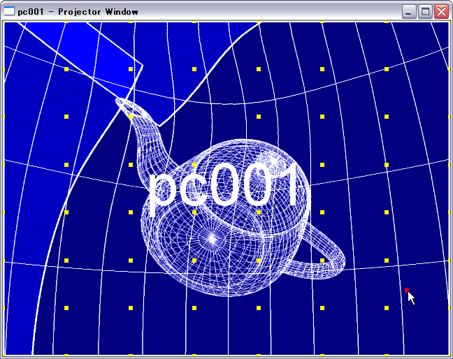
Select [Channels] tab in GUI panel, and then check [Enable] check box in [Warp] group. Click [Open Window…] button to open Projector Window on the server PC. Since you activated the warp flag, you’ll see yellow control points in the Projector Window. You can tweak the projection image directly by dragging these yellow control points. If you want more control points, set [Res.] value in [Warp] group. Notice that when you change the number of control points, the current setup of control points will be discarded. You can reset the control points by clicking [Reset] button.
Make a blend map
 When you use multiple projectors, you’ll notice that projector’s overlapped area will becomes brighter. To equalize intensity on the screen surface, you need to make a blend map which represents darken overlapped area.
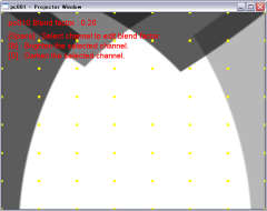
To make a blend map in ProjectionDesigner, select [Edit] > [Blend Map] in menu to switch to blend map editing mode. In the actual projection environment, you’ll see the white images of all projectors cause undesirable intensity distribution. Select a channel to make a blend map in the channel list in [Channels] tab, click [Open Window…] button to open Projector Window. Click somewhere in the window and hit [Space] key to confirm switching selected blend channel name displayed at the upper left corner. Now select a channel which overlapped on the current channel by hitting [Space] key some times. You can darken the blend channel by hitting [B] key. Adjust the blend value by [B],[D] key until achieving flat intensity distribution on the screen surface.
You can smooth the blending edge for seamless intensity distribution. Select [Edit] > [Preference…] in menu to open Preference Dialog, check [Soft edge] in [Blend Map] group. You can also change width and intensity curve of the blending edge by editing [Width] and [Exponent] fields.
Export the Projection data set
 After finishing the projection setup, export the Projection data set to use it in other applications. Save the current data at first, then select [File] > [Export Data set…] in menu to export the data set. The Projection data set will be exported in the same directory as the data file saved like:
distort_CHANNELNAME.png
blend_CHANNELNAME.png
view_CHANNELNAME.cfg
You can change size of distortion map and blend map image. Select [Edit] > [Preference…] in menu to open Preference Dialog, and then change [Image size] value in [Export] group. You can also set file name pattern in the Preference Dialog. In the file name pattern setting, %CHANNELNAME% will be replaced to channel name, %CHANNELINDEX% to channel index, %REMOTEHOST% to remote host name.
Format of Projection data set
This chapter explains format specifications of the Projection data set.
Distortion map image
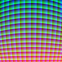 In distortion correction, you need to pre-warp a rendered image to make a projection image on a screen surface undistorted viewed from a sweet spot in your theater. Distortion map defines where each pixel in the projection image mapped from undistorted rendered image. Color value of each pixel in the distortion map image represents normalized coordinate in the rendered image.
X = ( B / 255 + ( R mod 16 ) ) / 16.
Y = ( G / 255+ ( R / 16 ) ) / 16.
Here, X and Y is normalized coordinate (0.0-1.0) in the rendered image, R, G and B is color element value in the distortion map (0-255). You can use this formula in your shader code or texture mapping coordinate generation code to realize the distortion correction.
Blend map image
 In multiple projector environments, you need to darken overlapped area of projectors to flatten intensity on the screen surface. Blend map represents intensity distribution and color correction for the projection image. You should multiply this blend map image to projection image which is pre-warped by the distortion map.
View matrix file
View matrix file defines View’s model/view matrix and projection matrix of a channel for rendering in your 3D application.
This file is a simple text file nested by ‘{‘ and ‘}’ blocks. The most outer block is "Channel" like this:
Camera “CHANNELNAME” { … }
In this block, the following "Lens" block represents a projection matrix of the View.
Lens {
Frustum <left> <right> <bottom> <top> <znear> <zfar>
}
Frustum’s parameter format is same as glFrustum() function in OpenGL.
Model/View matrix is defined in an "Offset" block, which may contain "Translate" and "Rotate" lines in order of operations.
Offset {
Transform <x> <y> <z>
Rotate <angle (degree)> <x> <y> <z>
}
These Translate and Rotate formats are also same as glTranslate*() and glRotate*() functions in OpenGL.
This View matrix file format is a subset of Open Producer’s camera configuration file. So you can use it as it is in Open Scene Graph based applications.
Build
Dependencies
To build ProjectionDesigner by yourself, you have to prepare the following libraries.
- Trolltech Qt library ver. 4.2 or later
- Download the latest Trolltech Qt library from its web site: http://www.trolltec.com/.
Todo
- More stability. Avoid redundant renderings.
Future Plans
- Automatic calibration (for free) ?
- etc...
Change Log
- 2007/4/10 Projection Designer version 1.1.0 beta. Remove GLRC, DevIL, Glee and libQGLViewer dependencies. Split the scene renderings as a plug-in. Key shortcuts not worked?
- 2006/7/15 Projection Designer version 1.0.0, the first public release.